ROVolution Blog

Print in Place Gripper Refined V2 Coupler Test

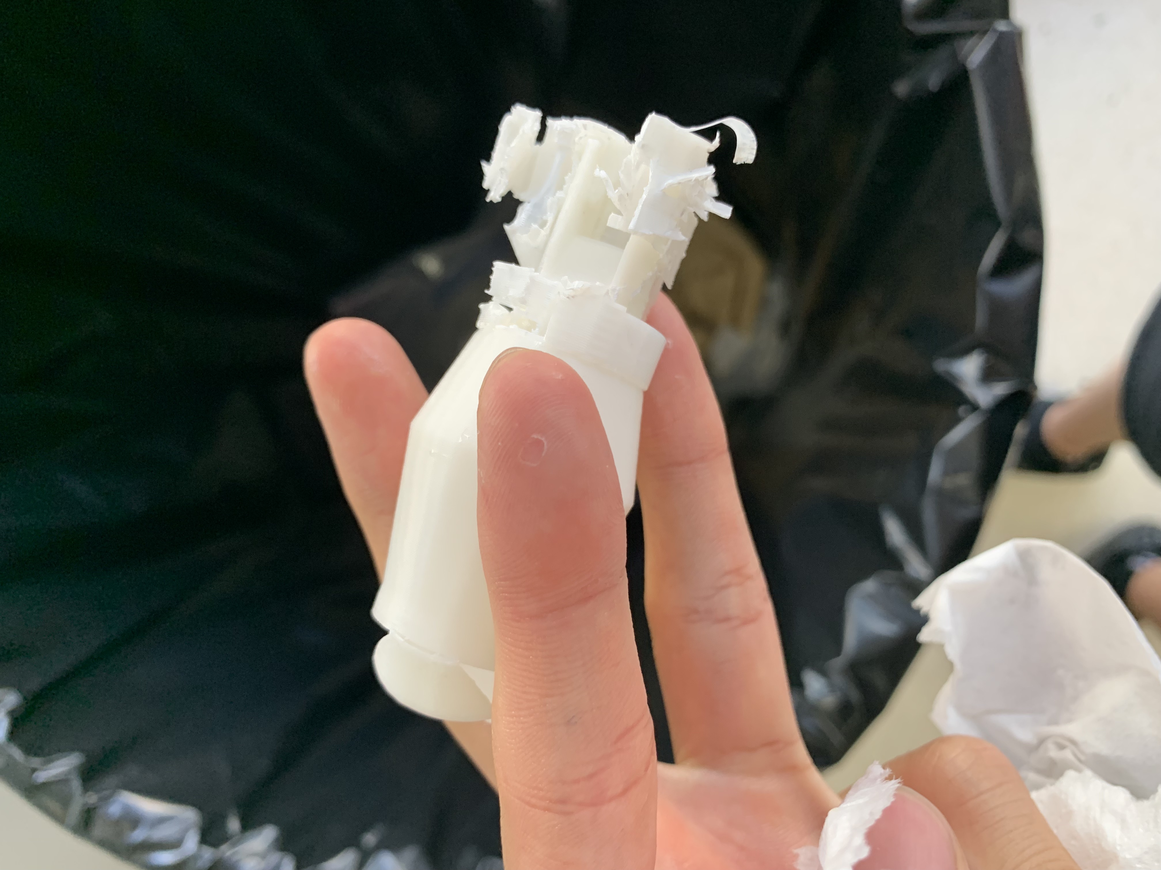
I discovered print in place mechanisms. Thus I wanted to try and make a coupler that is printed in place that allows for force that is applied linearly while simultaneously allowing rotary motion. I drew inspiration from the Kaleidocycle (link) and designed my own as seen in this video. I printed this in our school’s new printer, which came out great as seen in the image below (although it was quite difficult to get the supports off. I requested tree support from our manufacturing team and somehow it came out to be normal support). I found that it was not viable for our situation as seen in this video. The rotary motion of the coupler was fine, but the problem mainly lay in the linear force. When applying a linear force, the inner piece sort of gets stuck in the outer piece, which doesn’t allow it to rotate. I tried to put water in to see if I could improve it with some lubricant, but it didn’t work as well. I will use the original coupler.

Blog image
aa

Fish Catcher Prototype

Today, I worked on making the CAD model for the fish catcher. The image below shows a drawing that David made, which the model would be based on. The first model I created was made from 2 ovals, however, it was later switched to a more rounded rectangle shape. After creating these shapes, I made the hinge mechanism, which will try to be a print-in-place mechanism. This is in an attempt to make manufacturing much easier. The final product will put a net on either side, one being flat and the other being like a fish net extending to the back. It will use a waterproof servo to close. To finish the product, I need to test the print-in-place mechanism, add the compliant mechanism, and add bolt holes to hold the net.

STEP file

Blog image
aa

Gripper Refined V1 Complete Print

I modified the main linear mechanism by adding gears and a container for the linear actuator. Because I didn’t have the CAD file for the linear actuator, I found it quite difficult to model and properly make a container for it that would keep the linear actuator from moving at an angle. As you can see in this video, it was a complete disappointment and a waste of PLA. The print was also very low quality as we were in a hurry (here is the STEP file). Additionally, I had not considered the electrical side of this problem. To test the entire gripper, I headed to Konstantin’s house. For the design to work, I expected the linear actuator to be able to stop at a certain point, but this is very difficult given that it only has two power wires without any signal or something that is able to detect the extension. Thus, when retracting the linear actuator to close the gripper, we found that the linear actuator actually crushes the print and completely broke the coupler while squashing the slider piece. Also, I noticed that the linear actuator axle couldnt retract fully (though it wasn’t a large difference if you see the image below), suggesting that it has probably skipped a few gears internally. When I left, the electrical engineer was able to fit the gear onto the M200 motor and was able to rotate the gripper as seen in this video. We had a discussion and decided the best way to reduce the chances of breaking the gripper was to add a stiff spring that wouldn’t allow the linear actuator to skip gears for some time while there is current sensing to see if there is excess force applied. From this experience and the feedback given from the electrical engineer, there should be changes such as:

  • Increased tolerance for the parts that are connected to the components such as the linear actuator housing or gear held by the M200
  • Decreased tolerance for parts that are related to the axle
  • Remove the sliding component that attaches to the linear actuator housing and replace with something else
  • A spring mechanism
  • A gripper that has a long axle
  • The use of the linear actuators' built-in stopping point helps prevent damage to components by avoiding crushing
Blog image
Blog image
aa

Testing new equipment

Today we tested 2 new pieces of equipment, the HDPE and the pump. For the HDPE we wanted to make sure it was positively buoyant. Me and ati clogged a sink, and filled it up with water. Then we put the HDPE panel in, and made sure it floated, which it did. Next for the pump where there are 2 things me and Ahmed tested for. Firstly if the pump worked, and secondly if we could store the water in a container. We filled a cup with water, and tested the pump normally, and it worked. However, when we added the container to the pump, no water was being sucked in from the cup. We realized this was because there were open holes in the container, meaning air was pumped instead of water. So to test our idea, we first covered the holes in scotch tape. Once we realized this was the issue we wanted a more permanent solution, so we epoxy sealed every hole around the container.

Blog image
aa

Meet the Sponsors

Today, David, Ahmed, and I, worked on creating the meet-the-sponsors posts for the Instagram accounts. We found two different Canva templates, and worked on those. Following the completion of the design, Ahmed reached out to our sponsors to get their confirmation of the posts. After the final edits, we posted them on our Instagram account.

Blog image
Blog image
Blog image
Blog image
Blog image
blah

Gripper Refined V1 Closing Mechanism

Gripper V1 is the first prototype compatible with our electrical components: Bluerobotics M200 motor and HAKIWO IP68 Waterproof 12V Linear Actuator. We chose the linear actuator as the opening and closing mechanism mainly because it is seen in other products like BlueRobotics and Reach Robotics. It could provide adequate force and speed without expensive parts due to the waterproofing. The gripper was designed to be able to hold round objects up to 3 inches in diameter. It has been designed to be as compact as possible, with the linear actuator axle coupling directly to the gripper mechanism. As the linear actuator’s axle is only 50 mm and the gripper extension mechanism is around 20 mm, we have to fit everything (the couple, the boot, and the gear/gripper holder) in 30 mm only. To save space, the coupler is placed between the gear/gripper holder and the gripper. I have also tested it (video), and found that I needed to decrease the clearance. Here is the STEP file.

later