ROVolution Blog

Metal Laser Cutter Final Pieces

With great success from our last session, we decided it was time to cut our final pieces. We liaised with the PCL inventory to acquire a full new sheet of aluminum for our purposes, and travelled to the HFL to set up the machinery for our purposes. After exporting the aluminum flat patterns as DXF files, and transferring them to the machinery, we were ready to cut. It was during the cutting we realized a mistake on our part. Whilst cutting out the voronoi pattern on the aluminum, the cut pieces didn’t fall through, which sometimes hindered the machine, hence we had to manually stop the machine and remove those pieces every time before continuing. However this was easy as the laser cutter had an extremely high precision and the aluminum was locked in place. Once we were done, we removed the pieces and began to sand it for safety purposes, however we had to stop due to time restrictions. Our plan moving forward would be to come in next week on a Monday to sand/finish the aluminum, bend it to our specifications and use the waterjet if we have enough time.

Blog image
Blog image
Blog image
Blog image
Blog image
Blog image
aa

Finalizing Cut Files

With plans to cut the final frame very soon, we took a trip to the PCL one more time in which we had a 90 minute sessions with the chief engineers and designers to fully solidify our design, ensuring there are no points of failure, and that we are able to easily manufacturer it with the PCL facilities. This involved taking precision measurements of the aluminum, and accounting for the bending. Thankfully this was all correct, and then we moved onto the bending process. We initially planned on “etching ” into the aluminum to aid us with the bending process, however this machine lacked those capabilities, thus we decided to take more precision measurements of where the bends begin, which we can input into the bending machine for ease. I unfortunately had to leave shortly after finalizing how to bend the aluminum, however my colleague Atisam stayed behind to test this process to ensure this will be feasible in the future.

aa

Learning to Aluminium Bend

Today I visited the HFL (Harbor Fabrication Lab) to learn how to use the Accurpress machine. This machine is used for bending sheets of Aluminium. This will be a vital process for our frame manufacturing which will involve two sheets of bent Aluminium. I worked with Woodrow from PCL to learn how to first use the machine. The way it works is pretty ingenious and involves a hammer piece pressing into a mold piece. The machine works by having the operator press down to push the Aluminium together at an angle. I practiced the specific cuts we would need for the ROV frame on spare Aluminium sheets that were available at HFL. The specific cut angle I really wanted to practice was the 135o angle bend. This was difficult because such an angle often distorted the shape of the Aluminium sheet making it harder to bend the next piece. The biggest thing I learned that will be vital for the actual bending process is to always start by ending the inner pieces first. This way the alignment of the outer bends is not affected too much by what is happening on the inside. This makes it much easier to ensure secondary and tertiary bends are done precisely.

aa

Training on Metal Laser Cutter and Learning about Clearance Holes

With the deadline for the frame fast approaching, we decided to learn the process of laser cutting metal and testing out the bolt holes, to fundamentally understand how we would manufacture our ROV frame, and take notes of any questions or issues we ran into. By doing this, we hope to eliminate any points of failure whilst constructing and fabricating the frame, whilst also changing the design to meet the specifications of the machinery available to us.

Hence we took a trip to the PCL, where we contacted one of their staff to aid us with this experiment/learning. We had beforehand sent them a test file, filled with different variations of clearance holes to determine which best suited our needs. It was here we learnt that they had an industry standard for the machinery they used, hence we changed the file according to their specifications; m3 bolts had a clearance size of 3.3 mm, whilst m6 bolts had a clearance of 6.5 mm. Once corrected, we transferred to the Harbour Fabrication Lab (HFL), where we were introduced to the 6KW “Fiber Laser Cutting Machine”, and learnt about the different processes it was capable of. Unfortunately, as 16-year old PCL users, we were not allowed to directly use the machine, but rather watched as the staff aided once. Once the lasercut was finished, we sanded the sharp edges (for safety purposes), and tested the bolt holes. We noticed that the m3 bolt holes were perfect, however there was a little too much wiggle room for the m6, hence in the actual design, we decided to change the m6 clearance hole to 6.4 mm.

This is a video

Blog image
aa

Use of Compliant Mechanism in Tooling

After developing a fascination on compliant mechanisms from prior research on mechanisms, I wanted to implement such mechanisms into this project. The materials we had at PCL were quite limited. Nylon 12 filament was almost used up and the rest was exposed to air while PETG didn’t work properly. Thus, our only option for a reliable compliant mechanism would be TPU.

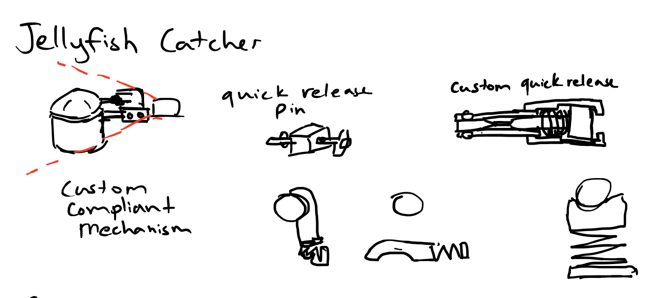
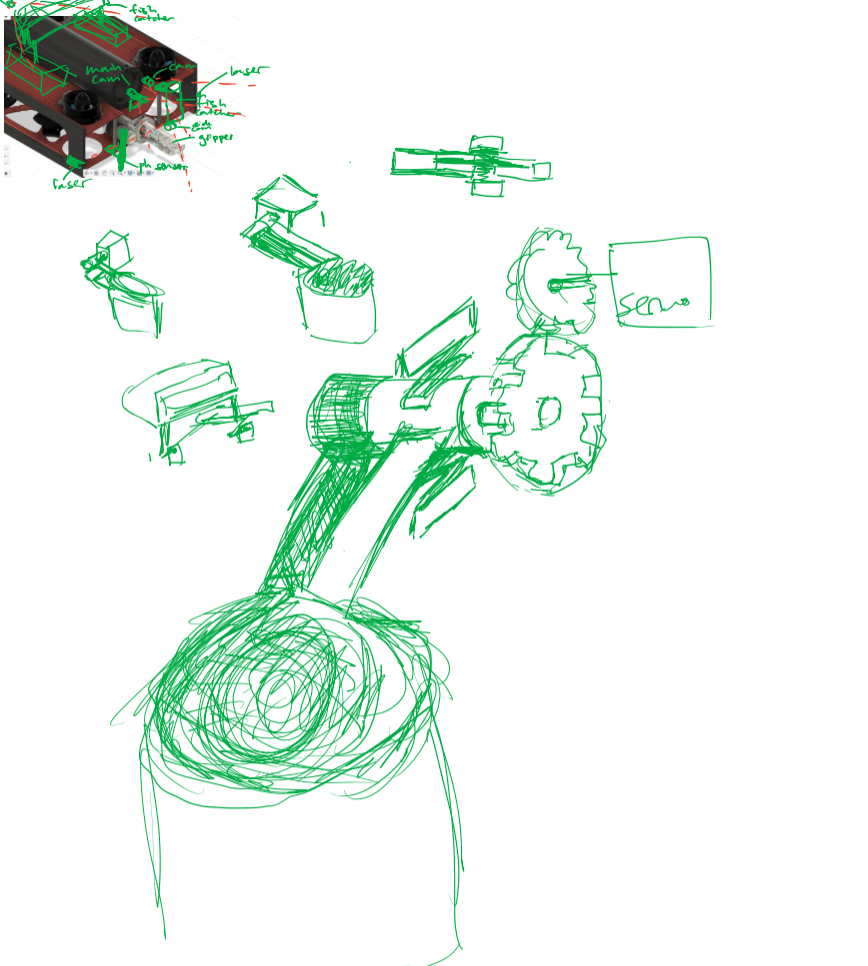
After reading the competition manual, I realized that the fish catcher and jellyfish catcher should be removable. A way to do this is to have a compliant mechanism hold it in place. This idea was extremely complex, but potentially could allow for the easiest removability with reliability that came with testing. This idea is outlined in the two sketches below. The opening and closing motion of the jellyfish catcher lid or the fish catcher lid would come from an axle that runs through a hinge, with one end connecting to the lid and another to a gear. The outer component of the hinge is connected to the “bucket” and would also reduce the horizontal motion of the inner axle. The compliant mechanism could hold the outer hinge in place, though with certain force could allow the entire hinge to be removed (the compliant mechanism should connect to the hinge perfectly, eliminating horizontal and rotational motion of the hinge with bumps). Finally, the gear is connected to a servo motor with another gear (the servo is not removable as the power source needs to be connected to the capsule). This allows for the removal of both the lid and the “bucket” in one go. This is the reason why the compliant mechanism is very important, and can make tooling removal very simple.

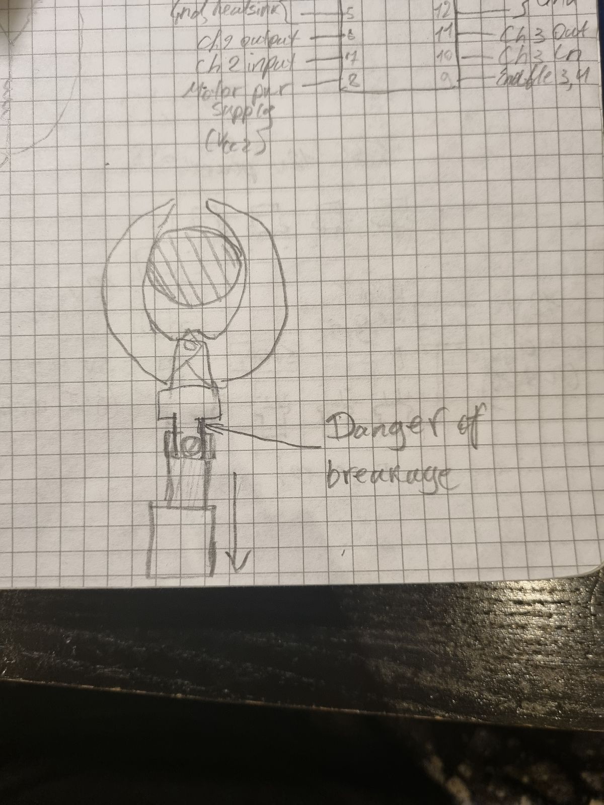
Compliant mechanisms can also act like springs, allowing movement though increasing the force. During a test of the gripper, we realized that it is extremely difficult to control the precise motion of the linear actuator, and that it may continue to retract while it has already grabbed an object or continue to extend even though the gripper can’t open any further. This could permanently damage both the 3D printed gripper and the linear actuator (shown in one of the sketches below). My friend thought of implementing a compliant mechanism that would allow for deformation during additional force. On top of current sensing, this adds another layer of protection for the gripper in case the pilot extends or retracts the gripper too much.

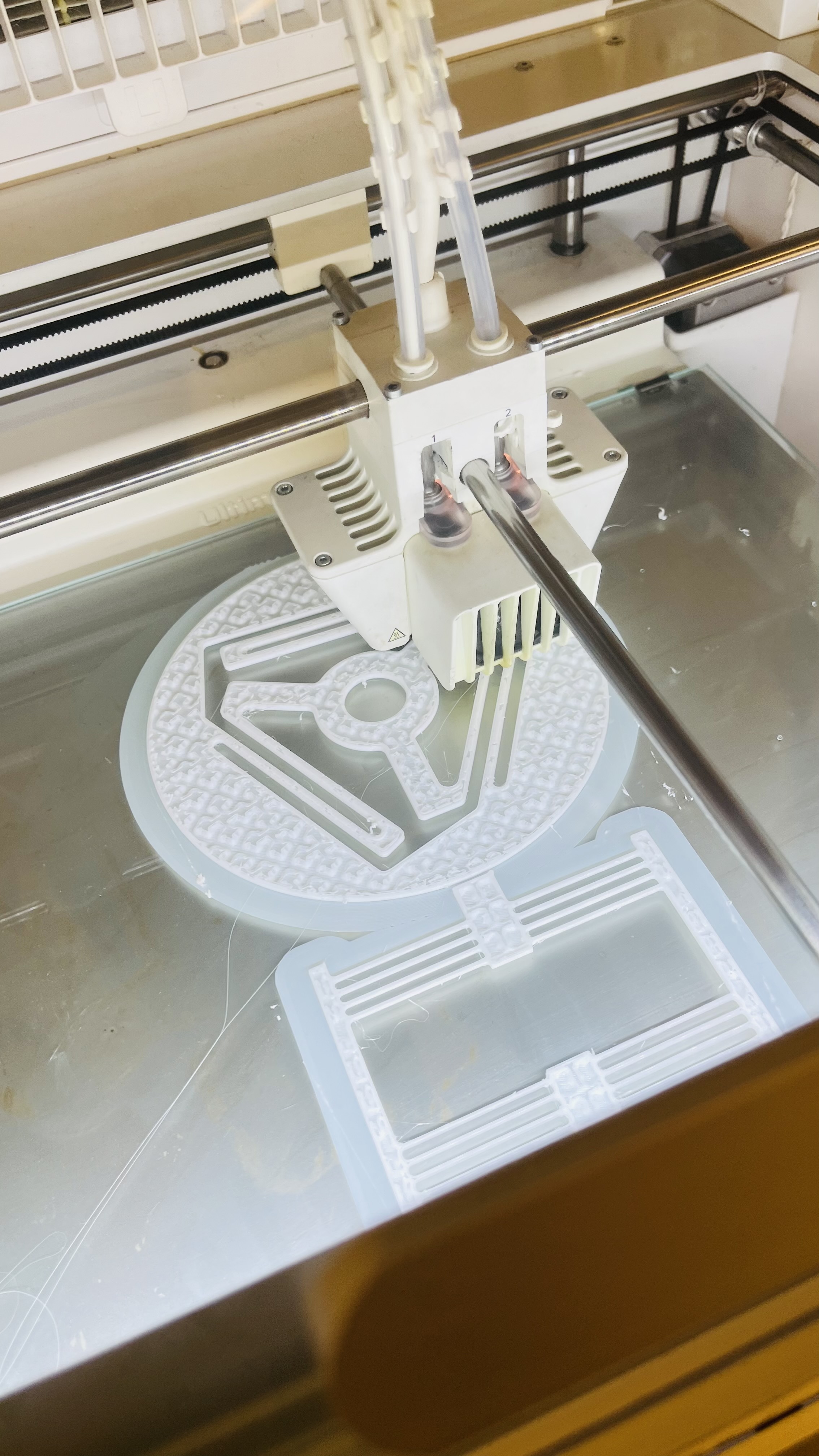
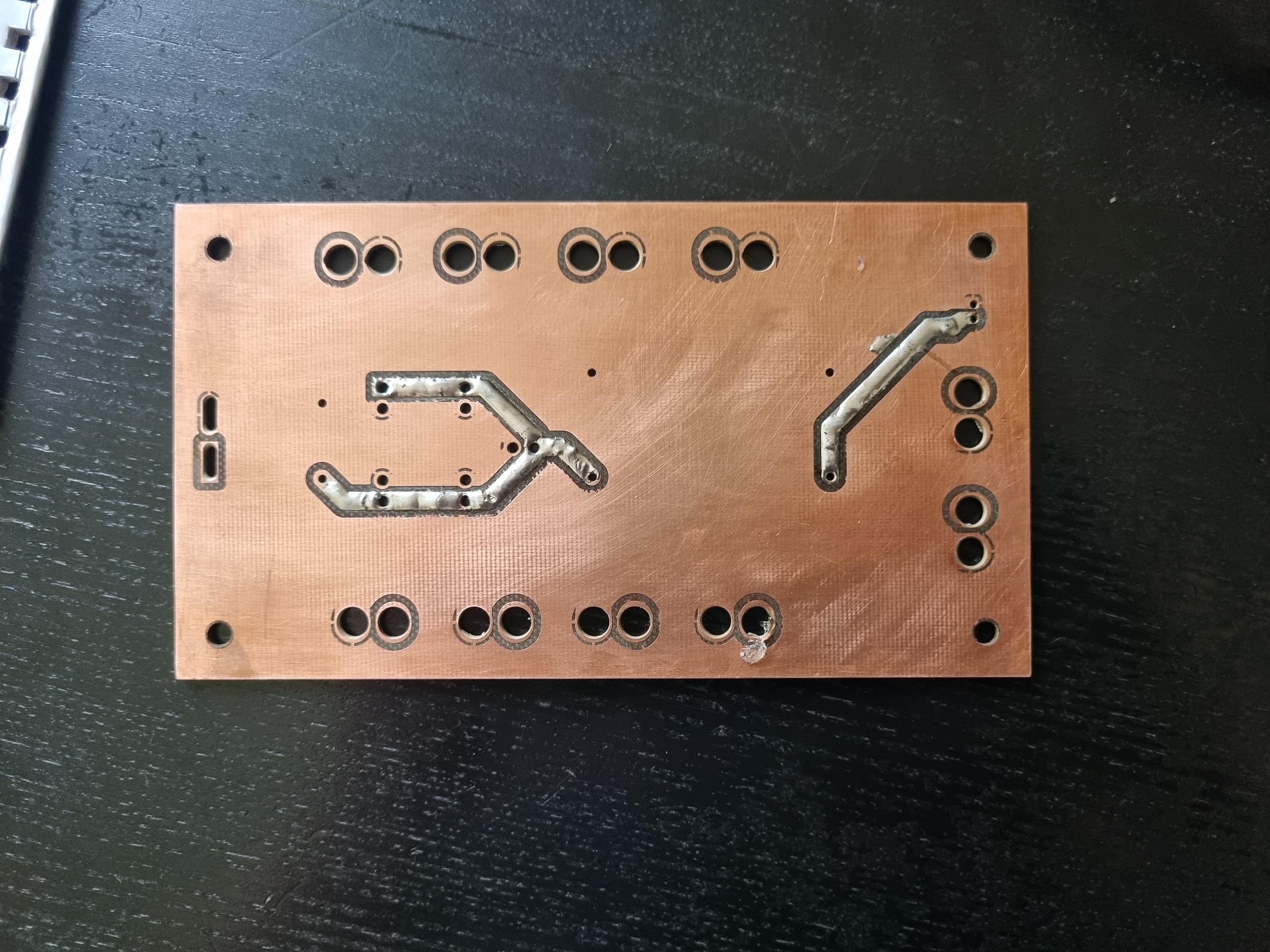
Thus, to test the properties of TPU and the use of compliant mechanisms, I sent a large-displacement linear-motion mechanism (CT) and an ortho-planar spring made by BYU to the manufacturing division of ROVolution to print at PCL with 30% infill. This can be seen in the images below. It came out very satisfactory, but was a lot more flexible than I thought. I believe that this is too unreliable for the tooling removal, but is very suitable for a spring system for the gripper. This is demonstrated in this video.

Blog image
Blog image
Blog image
Blog image
aa

Power Distribution PCB Fabrication

The Power Distribution PCB was manufactured at KAUST’s Electronics Fabrication Laboratory (EFL) using the LPKF suite of PCB prototyping equipment. The process has several stages: hole and outline cutting, hole plating, fabrication of tracks, and solder mask application.

Here is a video.

Blog image
Blog image
Blog image
Blog image
aa

Jelly Catching (One of the Tools)

For the most part, I was correcting and finalizing my design on Fusion 360. The design consists of a cylindrical tube for catching the jellyfish, and a lid that should close using a waterproof servos and gear. I had previously tested the hinges to ensure they work, however upon further analysis and brainstorming, I concluded that it would be an inefficient design, especially with the gears, hence I’ve made it simpler and easier to print (which was an added bonus). The next steps would include finding a way to secure the gears to ensure they work as intended, as well as printing a prototype (likely out of PLA), to test the design.

aa

Peg Board (Tooling Mobility)

Today I worked largely on Fusion 360 making changes to the design for the tooling Peg Board. The design was previously finalized with the utilization of aluminum standoffs to connect the board to the Aluminum sheet metal. However, we heard back from PCL who unfortunately did not have any standoffs of any kind. So I spent today reworking the design and coordinating with Ahmed to figure out an alternate solution that would still be able to deliver the requirements of the Peg Board.

aa